
 EN
EN



Selecting the right flat bed CNC lathe is one of the most critical decisions a precision metalworking shop can make. A flat bed CNC lathe directly impacts production efficiency, part quality, and long-term profitability. The wrong choice can lead to costly mistakes, wasted material, and missed deadlines. This guide walks you through the essential factors that distinguish an effective flat bed CNC lathe from one that fails to meet your operational needs.
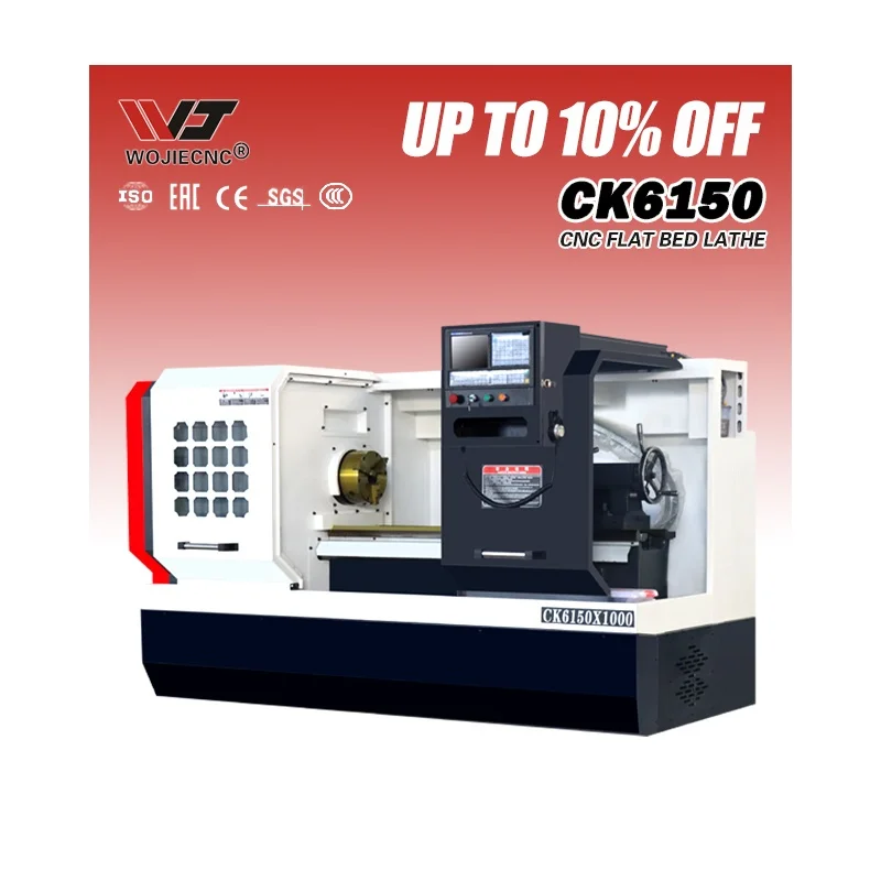
The flat bed CNC lathe remains the backbone of modern precision machining operations across automotive, aerospace, medical device, and general manufacturing sectors. Whether you are replacing aging equipment or expanding capacity, understanding the key selection criteria ensures you invest in a machine that delivers accuracy, reliability, and cost-effectiveness over its operational lifetime.
Understanding Flat Bed CNC Lathe Fundamentals
Core Design and Structure
A flat bed CNC lathe features a horizontal spindle axis and a rigid casting bed that provides exceptional stability during high-precision cutting operations. The flat bed design, as opposed to slant bed configurations, offers superior thermal stability and easier chip management. When evaluating a flat bed CNC lathe, the bed rigidity directly correlates with dimensional accuracy and surface finish quality. The machine's foundation must resist vibration and maintain geometric accuracy under sustained cutting loads.
Key Operational Advantages
The flat bed CNC lathe excels in applications requiring consistent dimensional tolerance and repeatable surface finishes. This machine type accommodates longer workpieces more naturally than slant bed alternatives and simplifies manual tool access for maintenance. Many precision shops prefer the flat bed CNC lathe because it reduces setup complexity and accelerates job changeover. The horizontal orientation of the spindle makes chip evacuation more predictable, reducing tool wear and extending tool life significantly.
Critical Specifications for Selection
Spindle Power and Speed Range
Spindle power determines your flat bed CNC lathe's ability to handle difficult materials and aggressive cutting conditions. Most industrial flat bed CNC lathe models range from 8 to 25 horsepower, depending on chuck size and cutting envelope. The speed range should match your typical workpiece geometry and material hardness. A flat bed CNC lathe with insufficient spindle power will stall during deep cuts, produce poor surface finishes, and force operators to reduce feed rates, negating production efficiency gains.
Chuck Size and Workpiece Capacity
The chuck diameter on your flat bed CNC lathe determines maximum workpiece diameter and clamping force. Standard flat bed CNC lathe chuck sizes range from 125 mm to 250 mm, with larger chucks handling heavier stock but requiring proportionally more spindle power. Consider your most challenging part dimensions, not your average part size, when selecting chuck capacity. A 6-inch chuck on a flat bed CNC lathe accommodates most general manufacturing parts, while aerospace applications often demand 8-inch or 10-inch configurations.
Precision and Repeatability Metrics
Positional accuracy and repeatability are non-negotiable specifications for a flat bed CNC lathe intended for tight-tolerance work. Modern flat bed CNC lathe machines achieve radial accuracy within 0.01 mm and longitudinal accuracy within 0.005 mm. Thermal compensation systems on advanced flat bed CNC lathe units help maintain accuracy across extended production runs. Request machine specifications that quantify bidirectional accuracy and verify these claims through sample parts produced under real cutting conditions.
Matching Machine Capabilities to Production Requirements
Material Compatibility and Cutting Performance
Your flat bed CNC lathe must handle the material spectrum your shop processes. A flat bed CNC lathe optimized for aluminum differs significantly from one designed for stainless steel or cast iron. Each material demands different spindle speeds, feed rates, and coolant systems. When evaluating a flat bed CNC lathe, confirm that its spindle power, speed range, and tooling options support your material mix without requiring constant parameter adjustment or tool changes that disrupt production flow.
Production Volume and Cycle Time
Production volume directly influences flat bed CNC lathe selection decisions. High-volume production demands faster cycle times, automatic tool changers, and robust chip-handling systems that differ markedly from low-volume job shop requirements. A flat bed CNC lathe configured for mass production may prove inefficient in a prototype-focused environment, and vice versa. Analyze your typical part complexity, batch sizes, and annual part count to ensure your flat bed CNC lathe investment scales appropriately with demand.
Maintenance, Operator Skill, and Support Infrastructure
Selecting a flat bed CNC lathe also requires evaluating manufacturer support, spare parts availability, and training resources. Machines from established manufacturers include comprehensive documentation and responsive technical support critical for minimizing downtime. Your flat bed CNC lathe operator skill level should align with machine complexity; a highly automated flat bed CNC lathe demands advanced programming knowledge that simple models do not require. Budget for ongoing training and factor long-term support costs into your flat bed CNC lathe purchase decision.
Practical Decision Criteria
Budget Allocation and Total Cost of Ownership
A flat bed CNC lathe represents significant capital investment, typically ranging from $40,000 to $200,000 depending on specifications and automation level. Calculate total cost of ownership by including maintenance, tooling, coolant, and operator training expenses beyond the initial machine purchase. A cheaper flat bed CNC lathe with poor reliability destroys profitability through production interruptions and scrap generation. Invest in a flat bed CNC lathe from a reputable manufacturer that balances initial cost with proven reliability and support quality.
Space, Utilities, and Infrastructure
Your flat bed CNC lathe installation site must provide adequate electrical service, compressed air capacity, and coolant disposal infrastructure. Space requirements for a flat bed CNC lathe extend beyond the machine footprint to include chip management, part loading and unloading areas, and tool storage. Poor planning creates dangerous crowded shop floors and limits your flat bed CNC lathe's operational flexibility. Verify facility compatibility before committing to a flat bed CNC lathe purchase.
Scalability and Future Flexibility
Select a flat bed CNC lathe that accommodates your anticipated growth and evolving production demands. Modular tooling systems and adaptable work-holding options allow a single flat bed CNC lathe to handle diverse part geometries over time. Avoid oversizing unnecessarily, but ensure your flat bed CNC lathe selection leaves room for expanded capabilities without requiring complete machine replacement within five years.
FAQ
What makes a flat bed CNC lathe different from a slant bed machine?
A flat bed CNC lathe features a horizontal bed that provides superior thermal stability and easier chip management compared to slant bed designs. The flat bed CNC lathe maintains tighter tolerances across extended production runs and simplifies manual tool access. Slant bed machines offer faster spindle speeds and more compact footprints but sacrifice some thermal stability. Choose a flat bed CNC lathe when precision and chip control take priority over speed and floor space.
How do I determine the right spindle power for my flat bed CNC lathe?
Spindle power requirements depend on material hardness, cutting depth, and feed rate combinations typical in your shop. Calculate power needs by multiplying material removal rate by specific cutting force data for your material. A flat bed CNC lathe underpowered for your application will stall, produce poor finishes, and accelerate tool wear. Oversizing spindle power unnecessarily increases machine cost, but a well-matched flat bed CNC lathe delivers optimal efficiency and tool life.
What are typical maintenance requirements for a flat bed CNC lathe?
Routine flat bed CNC lathe maintenance includes daily chip removal, coolant monitoring, spindle lubrication, and linear guide way cleaning. Monthly inspections should verify spindle runout, axis repeatability, and manual chuck operation. A properly maintained flat bed CNC lathe maintains accuracy over thousands of production cycles. Establish preventive maintenance schedules aligned with machine manufacturer recommendations to maximize flat bed CNC lathe uptime and longevity.

